
By Michael Schilli
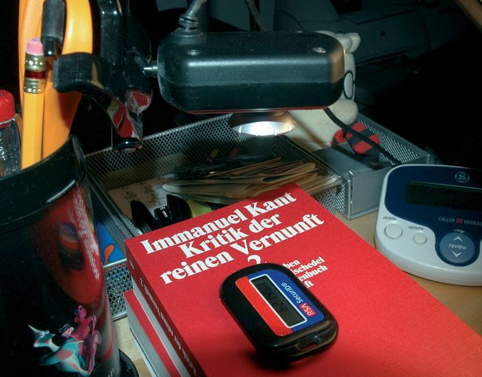
My colleague Fergus recently noticed that his SecurID token displayed "000000," and he posted a photo of this on Flickr [1]. These keyfob tokens by SecurID output a different 6-digit number every 60 seconds (Figure 1). If the odds for any numeric sequence appearing are equal, the chance of getting to see "000000" is one in a million. It's like winning the lottery!

This lucky shot made me curious to find out what my keyfob displayed while I wasn't looking. It is fairly easy to digitize the output with a webcam or a scanner (Figure 2), and optical character recognition (OCR) would give me the digits hidden in the pixel-based output. But because OCR vendors have more or less patented this area to death, there is little in the line of functional free software.
In this case, full-blown OCR is unnecessary because the token only displays the numbers zero through nine. The display is made up of just seven evenly spaced digits with seven fairly thick, black LCD segments each, and that makes the task easier - all it takes are a Perl script and the right CPAN modules.
Please note: the Fobcam [2] of a computer user who uses a webcam to show the current output from his SecurID token on his website because he's too lazy to carry the token with him is good for a joke, but nothing you want to imitate.
A webcam or scanner is needed to grab an image of the token. In a previous issue of this column [3], I pointed out how to control a webcam on Linux with the Video::Capture::V4l module. Now, a Video::Capture::V4l::Imager module is available from CPAN, and that makes things even easier.
The fobcam listing (Listing 1) shows how the Perl module controls the camera, starting by setting the required brightness with the brightness() method. The best value will depend on the camera type and the ambient light. After a couple of experiments, you should have a usable value. If you want to have the module figure out the best brightness setting, it also has a calibrate() method that tries different brightness() settings until the captured image matches the preset mean brightness.
The capture method then returns an Imager type object as a result, and you can either process the image data directly or store the results on disk in a popular format such as JPEG or PNG.
| Listing 1: fobcam |
01 #!/usr/bin/perl -w 02 use strict; 03 use 04 Video::Capture::V4l::Imager; 05 use Log::Log4perl qw(:easy); 06 07 Log::Log4perl->easy_init( 08 $DEBUG); 09 10 my $v = 11 Video::Capture::V4l::Imager 12 ->new( 13 width => 640, 14 height => 480, 15 ); 16 17 $v->brightness($ARGV[0] 18 || 27_900); 19 my $img = $v->capture(); 20 21 $img->write( 22 file => 'fob.jpg') 23 or die "Can't write: $!"; |
For character recognition purposes, we first need to determine the position of the keyfob display in the image and calculate the position of the individual digits. After discovering the coordinates of the rectangle containing the seven LCD segments that make up each number, the recognition script defines a sensor for each segment to measure the brightness values of individual pixels near them (Figure 3). If the sensor returns a high value, the matching segment is inactive. If a low RGB value is returned, the image has a dark patch, and assuming that the lighting is okay, this indicates an active LCD segment.
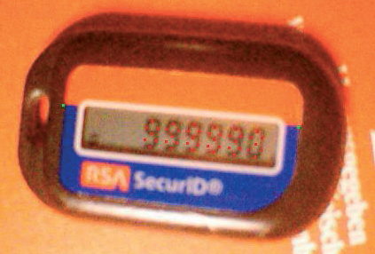
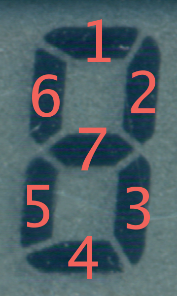
Figure 4 shows a single LCD digit. The segments have been numbered somewhat arbitrarily to refer to them individually in the program. For the number 8, all segments have to be active, whereas just segments 2 and 3 are lit for the number 1.
Practical experience revealed that the token was not always straight in the image, that the cheap webcam has astonishingly poor close-up image quality, and that the lamp on my desk used to illuminate the scene doesn't exactly resemble clean room conditions. Time to dig into my bag of tricks.
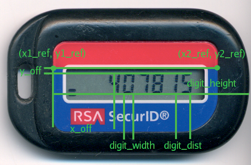
To determine the positions of the individual segments within the image, the recognition script first has to get its bearings in the image. To do so, I used the two outer top corners of the blue area shown in Figure 5 as reference points. Their pixel coordinates (x1_ref, y1_ref) and (x2_ref, y2_ref) are passed in to the recognition script.
If you care to experiment with this, a Blue.pm module is available with the listings for this article [4]. The script uses a simple approach to discover the two reference points. Unfortunately, explaining exactly how this works would be way beyond the scope of this article. That said, you can just as easily use GIMP to find the coordinates by loading a test image and hovering the mouse over the reference points. GIMP will show you the X/Y coordinates in the bottom left-hand corner of the window.
The two reference points make it easy to uniquely identify the position of the token in the image. Of course, every keyfob has slightly different dimensions, and the resolution will influence the values for the distances between the reference points and the segments even if you use the same token.
Because of the problems stated above, the script does not hard-code the dimensions; rather, it uses the fobs.yml configuration file to manage them (Listing 2).
| Listing 2: fobs.yml |
01 # Key Fob Characteristics 02 RSA1: 03 x1_ref: 176 04 y1_ref: 232 05 x2_ref: 422 06 y2_ref: 155 07 x_off: 99 08 y_off: 9 09 digit_width: 12 10 digit_height: 27.5 11 digit_dist: 23 12 digits: 6 |
The horizontal distance between the first reference point of a token sitting perfectly straight in the image (for calibration only) and the first digit in the display is specified by x_off. y_off is the vertical distance between the top row of the digit segments and an imaginary horizontal line that connects the two reference points (Figure 5).
The width of the LCD digits is defined as digit_width, and digit_height is the height. digit_dist is the horizontal distance from the start of one digit to the start of the next. Finally, digits specifies the number of digits shown in the display. The dimensions in fobs.yml are given in pixels, but the data is really independent of the screen resolution.
Before the script uses the dimensions, it first determines the distance between the real reference points in the actual image, compares them with the data in fobs.yml, and interpolates all values accordingly.
The script in Listing 3, reco, expects an image file and four coordinates for the two reference points of the current token in the current image:
$ reco fob.jpg 160 193 425 218
372394
The script then outputs the six-digit number that it has detected. To do so, it uses the LCDOCR.pm module (described later). The reco() method in LCDOCR.pm returns a pointer to an array containing the recognized digits.
| Listing 3: reco |
01 #!/usr/bin/perl -w
02 use strict;
03 use Log::Log4perl qw(:easy);
04 use LCDOCR;
05 use Getopt::Std;
06
07 getopts("vd", \my %opts);
08 Log::Log4perl->easy_init(
09  $opts{v} ? $DEBUG : $ERROR);
10 my ($file, $x1, $y1, $x2,
11  $y2) = @ARGV;
12 die "usage: " .
13   "$0 file x1 y1 x2 y2\n"
14   unless defined $y2;
15
16 my $i = Imager->new();
17 $i->read(
18  file => $file,
19  type => "jpeg"
20   )
21   or die "Can't read $file";
22
23 my $gr =
24   Imager::Color->new(0, 255,
25  0);
26 $i->circle(
27  color => $gr,
28  r     => 1,
29  x     => $x1,
30  y     => $y1
31 );
32 $i->circle(
33  color => $gr,
34  r     => 1,
35  x     => $x2,
36  y     => $y2
37 );
38
39 my $ocr = LCDOCR->new(
40  name   => 'RSA1',
41  x1_ref => $x1,
42  y1_ref => $y1,
43  x2_ref => $x2,
44  y2_ref => $y2,
45  image  => $i,
46  debug  => ($opts{v} || 0)
47 );
48
49 my $digits = $ocr->reco();
50
51 if ($opts{v}) {
52  my $font =
53    Imager::Font->new(file =>
54 "/usr/X11R6/lib/X11/fonts/TTF/Vera.ttf"
55    );
56
57  $i->string(
58   x      => 50,
59   y      => 50,
60   string => "Reco: @$digits",
61   font   => $font,
62   color  => "white",
63   size   => 30
64  );
65  $i->write(
66   file => "out1.jpg",
67   type => "jpeg"
68  );
69  system("xv out1.jpg")
70    if $opts{d};
71 }
72 print join('', @$digits),
73   "\n";
|
If the script starts in verbose mode (-v), it will draw the sensor locations into the image and also scribble in the recognized number. It will save the result in a file named out1.jpg, which can help calibrate the parameter settings if the sensors are not quite at the right locations. If you call the script with the -d command-line option, it will additionally launch the fast xv image viewer showing the image with the embedded information (Figure 3).
The LCDOCR.pm module implements the OCR process (Listing 4). To do so, it delves into the realm of the C programming language within the Imager module. You could use an XS file for this, as shown in my previous article [3], but the CPAN Inline::C module lets you embed C code directly into your Perl script.
| Listing 4: LCDOCR.pm |
001 package LCDOCR;
002 use strict;
003 use Imager;
004 use Log::Log4perl qw(:easy);
005 use YAML qw(LoadFile);
006
007 #############################
008 sub new {
009 #############################
010  my ($class, %options) = @_;
011
012  my $refd =
013    LoadFile("/etc/fobs.yml")
014    ->{ $options{name} };
015  my $self = {
016   name      => "RSA1",
017   threshold => 0.85,
018   debug     => 0,
019   digits => $refd->{digits},
020   %options,
021  };
022
023 # Adapt coordinates to real image
024  my $stretch =
025    ref_dist($self) /
026    ref_dist($refd);
027  for (
028   qw(x_off y_off digit_width
029   digit_height digit_dist)
030    )
031  {
032   $self->{$_} =
033     $refd->{$_} * $stretch;
034  }
035
036  $self->{angle} = atan2(
037   $self->{y2_ref} -
038     $self->{y1_ref},
039   $self->{x2_ref} -
040     $self->{x1_ref}
041  );
042
043  bless $self, $class;
044 }
045
046 #############################
047 sub ref_dist {
048 #############################
049  my ($h) = @_;
050  return sqrt(
051   (
052    $h->{x2_ref} -
053      $h->{x1_ref}
054   )**2 + (
055    $h->{y2_ref} -
056      $h->{y1_ref}
057     )**2
058  );
059 }
060
061 #############################
062 sub reco {
063 #############################
064  my ($self) = @_;
065
066  my @digits;
067  my %seg_orient = qw(
068 1 h 2 v 3 v 4 h 5 v 6 v 7 h);
069
070  for (1 .. $self->{digits}) {
071   my $coords =
072     $self->seg_coords($_);
073   my $segstring = "";
074
075   my $bkground = (
076    xybrightness(
077     $self->{image},
078     @{ $coords->{8} }
079      ) + xybrightness(
080     $self->{image},
081     @{ $coords->{9} }
082      )
083   ) / 2;
084
085   for my $c (1 .. 7) {
086    my ($x, $y) =
087      @{ $coords->{$c} };
088
089    if (
090     pixel_dark(
091      $self->{image},
092      $x,
093      $y,
094      $bkground,
095      $self->{debug},
096      $c,
097      $seg_orient{$c},
098      $self->{threshold}
099     )
100      )
101    {
102     $segstring .= "$c";
103    }
104
105    if ($self->{debug}) {
106     my $red =
107       Imager::Color->new(255,
108      0, 0);
109     $self->{image}->circle(
110      color => $red,
111      r     => 1,
112      x     => $x,
113      y     => $y
114     );
115    }
116   }
117
118   my $digit =
119     seg2digit($segstring);
120   push @digits,
121     defined $digit
122     ? $digit
123     : "X";
124  }
125
126  return \@digits;
127 }
128
129 #############################
130 sub seg_coords {
131 #############################
132  my ($self, $digit) = @_;
133
134  my $x =
135    $self->{x_off} +
136    ($digit - 1) *
137    $self->{digit_dist};
138  my $y = $self->{y_off};
139  my $w =
140    $self->{digit_width};
141  my $h =
142    $self->{digit_height};
143  my $r = sub {
144   [ $self->rotate(@_) ];
145  };
146
147  return {
148   1 => $r->($x, $y),
149   2 => $r->(
150    $x + $w / 2,
151    $y + $h / 4
152   ),
153   3 => $r->(
154    $x + $w / 2,
155    $y + 3 * $h / 4
156   ),
157   4 => $r->($x, $y + $h),
158   5 => $r->(
159    $x - $w / 2,
160    $y + 3 * $h / 4
161   ),
162   6 => $r->(
163    $x - $w / 2,
164    $y + $h / 4
165   ),
166   7 => $r->($x, $y + $h / 2),
167
168   # ref points
169   8 => $r->($x, $y + $h / 4),
170   9 => $r->(
171    $x, $y + 3 * $h / 4
172   ),
173  };
174 }
175
176 #############################
177 sub seg2digit {
178 #############################
179  my %h = (
180   "23"      => 1,
181   "12457"   => 2,
182   "12347"   => 3,
183   "2367"    => 4,
184   "13467"   => 5,
185   "134567"  => 6,
186   "123"     => 7,
187   "1234567" => 8,
188   "123467"  => 9,
189   "123456"  => 0,
190  );
191  return $h{ $_[0] };
192 }
193
194 #############################
195 sub rotate {
196 #############################
197  my ($self, $xd, $yd) = @_;
198
199  my $r =
200    sqrt(
201   $xd * $xd + $yd * $yd);
202
203  my $phi = atan2($yd, $xd);
204  $phi += $self->{angle};
205
206  my $xd_rot = $r * cos($phi);
207  my $yd_rot = $r * sin($phi);
208  my $x_abs  =
209    $self->{x1_ref} + $xd_rot;
210  my $y_abs =
211    $self->{y1_ref} + $yd_rot;
212
213  return ($x_abs, $y_abs);
214 }
215
216 use Inline C =>
217   <<'EOT' => WITH => 'Imager';
218
219 int pixel_dark(Imager im,
220     int x, int y,
221     int threshold, int debug,
222     int seg, char *direction,
223     float percent) {
224
225  i_color val;
226  int br, i, j, dark=0;
227  int min=-1, imin=0, imax=1,
228      jmin=0, jmax=1;
229  float rel;
230
231  if(direction == 'h') {
232    jmin = -1; jmax = 2;
233  } else {
234    imin = -1; imax = 2;
235  }
236
237  for(i=imin; i<imax; i++) {
238    for(j=jmin; j<jmax; j++) {
239      i_gpix(im, x+i,
240             y+j, &val);
241      br = brightness(&val);
242      if(min == -1 ||
243         min > br)
244        min = br;
245    }
246  }
247
248  rel = 1.0*min/threshold;
249  if(rel < percent)
250   dark = 1;
251
252  if(debug) {
253   printf("TH[%d]: %d "
254          "(%d %.1f%%: %d)\n",
255     seg, min, threshold,
256     rel*100.0, dark);
257  }
258  return dark;
259 }
260
261 int brightness
262   (i_color *val) {
263   return((val->channel[0] +
264       val->channel[1] +
265       val->channel[2])/3);
266 }
267
268 int xybrightness(Imager im,
269               int x, int y) {
270   i_color val;
271   i_gpix(im, x, y, &val);
272   return brightness(&val);
273 }
274
275 EOT
276
277 1;
|
The first time the script is called, the C code is compiled transparently for the user, and the object and shared library files are stored in the _Inline subdirectory. The next time you launch the script, the compiler step is not needed, and the script will launch at full speed. If the C code in the script changes, Inline::C notices the changes and recompiles.
To calculate the token's angle of rotation relative to the border of the image from the reference points, the new constructor uses a couple of simple trigonometric functions. The distances between the coordinates are the legs of a right-angled triangle; thus, the angle of rotation can be calculated as the tangent of the quotient from the opposite leg to the adjacent leg (Figure 6). Perl does not have a native atan function, but it does have atan2(), which accepts both leg lengths separately.

Because the token does not need to be aligned perfectly in the image, the character recognition script spins its detection web horizontally and uses the rotate() function to rotate it to the angle of the token, which is known at this point because we know the location of the two reference points within the real image. Rotation in a Cartesian coordinate system is a bit tricky to calculate. It's easier to convert the Cartesian coordinates to polar coordinates r and phi (Figure 7). The radius r is calculated by Pythagoras' theorem and the angle of rotation phi from the tangent of the quotients of the Y and X values.
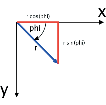
Line 204 then adds the known rotational angle of the token to this angle phi before the following lines convert the coordinates back to Cartesian values by simple trigonometry (sine, opposite leg, hypotenuse). This gives us the rotation of the OCR mask about the center of rotation [x1_ref, y1_ref].
The seg2digit() function determines the digits by reference to a string of sorted ordinals for the active segments. Sorting facilitates access - if the script determines that segments 2 and 3 of an element are black, a call to seg2digit() with 23 returns 1 after a simple hash lookup, which is exactly what the display reads. If the segment numbers don't make sense and no digit can be recognized, seg2digit() returns a value of undef, and the main program converts this to X. This tells you that you need to adjust something (double-check the sensors) or that the lighting conditions need to be improved to increase contrast between the light background and the dark segments.
If the display is not lit evenly, the light background can have different brightness values, and that makes it difficult to choose a reliable threshold value to distinguish between active and inactive segments.
For this reason, the reco method not only measures the pixel brightness at the positions in which segments are located, but at positions without segments in the center of the upper and lower rectangles of the figure eight (see Figure 4). These measurement points - number eight and nine - are interpreted by the script as the mean value of the background brightness of a segment.
The threshold parameter specifies how much darker than the background a measured value has to be for the routine to decide that it is an active segment. Let's assume that threshold is 0.85 and the background has a mean brightness value of 180. In this case, measured values of 153 or more would be classified as background, that is, as inactive LCD segments. Figure 8 shows how the digit "0" is detected with a threshold value of 0.85.
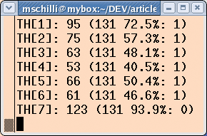
Active segments shown vary between 40.5 percent and 72.5 percent of the mean background brightness value of 131. In contrast, the inactive segment 7 has a brightness value of 123, which translates to 93.9 percent, slightly above the threshold value of 85 percent.
To identify the black segments in the display despite slightly displaced coordinates, the pixel_dark function in the inline C code measures the current pixel and neighboring pixels, and only takes the darkest values as measurements. To avoid measuring parts of the neighboring segment, the function measures values orthogonal to the segment. In the case of horizontal segments, it inspects the top and bottom pixels. In the case of vertical segments, it investigates the pixels to the left and right. The %segdir hash specifies the position of every segment by number to support this.
The brightness() function measures the brightness of a pixel value, adding the red, green, and blue components of the measuring point to do so. xybrightness() calculates the brightness at a given [x,y] coordinate.
The seg_coords($x, $y) function provides the X/Y coordinates for all segments in a digit, given that the middle of the top segment is located at the coordinates $x and $y. The return value is a pointer to a hash, which contains segment ordinals as keys and anonymous arrays of X/Y coordinates as values.
If you enable the debug option, the reco() function will draw the segment coordinates in the image (Figure 3). Of course, this happens after scanning because every single sensor would detect a red pixel otherwise. This information helps to fine tune the system.
To install, you need to download the required CPAN modules, Video::Capture::V4l::Imager and YAML. The CPAN shell will retrieve all other required modules. You have to store the LCDOCR.pm module somewhere that the reco module will find it (for example, in /usr/lib/perl5/site_perl). To capture the first image, you then type fobcam. With the use of GIMP, you can discover the reference points and add the data for the display you are using to the /etc/fobs.yml file, then launch reco with the name of the stored image file and the reference coordinates.
When adjusted correctly, the OCR system should start detecting rows of digits reliably, and you can start to evaluate the results. Remember, if you want to run the script at night, don't switch off your table lamp!
| INFO |
|
[1] "000000" on a SecurID token: http://www.flickr.com/photos/ferg2k/381185553/
[2] Fobcam: http://fob.webhop.net/ [3] Michael Schilli, "Fishing for Images," http://www.linux-magazine.com/issue/68/Perl_Controlling_a_Webcam.pdf [4] Listings for this article: http://www.linux-magazine.com/Magazine/Downloads/79 |